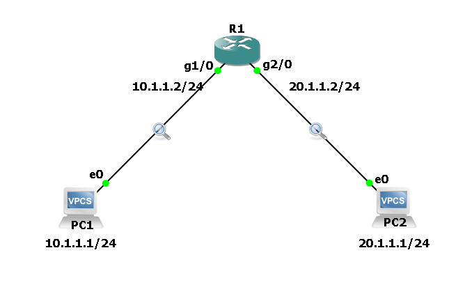
In this walkthrough, we’ll take a closer look at how packets travel between two PCs located on different networks and communicate through a router — making it easy to understand the packet flow process step by step.
In our previous blog, we explored how data travels between two PCs connected directly or through a switch. Certainly! Here’s a smooth and clear rephrasing of your sentence:
Network Topology and Address Table –
Here’s the lab setup we used to understand the packet flow. The diagram shows how two PCs (PC1 and PC2) connect to a router on different interfaces and subnets.

Each PC has a unique IP and MAC address in different subnets, with the router acting as the gateway connecting these two networks.
| Device/Address | PC – 1 | PC – 2 | R1 interface G1/0 | R1 interface G2/0 |
| IP Address | 10.1.1.1/24 | 20.1.1.1/24 | 10.1.1.2/24 | 20.1.1.2/24 |
| MAC Address | 00:50:79:66:68:00 | 00:50:79:66:68:01 | ca01.47c1.001c | ca01.47c1.0038 |
To begin with, I powered on all the devices and verified the IP address configuration. As shown in the screenshot below, no IP addresses were configured initially.
Therefore, the first step is to assign IP addresses to both the PCs and the router interfaces according to the topology described above.


I’ve assigned the IP addresses and highlighted the corresponding MAC addresses. On each PC, the default gateway is configured as the IP address of the connected router interface.


Step 1: Initial ARP Cache Status
Before starting communication, we checked the ARP tables on both PCs. They were empty because no communication has yet taken place. Since the MAC address is essential for sending data at the Ethernet layer, the PCs need to resolve the MAC of their destination.
When PC1 tries to contact PC2, it notices that PC2 is on a different subnet. PC1 doesn’t know PC2’s MAC address but it must send the packet to its default gateway (Router at 10.1.1.2). So, the first step is for PC1 to discover the MAC address of its default gateway using ARP.
Step 2: ARP Request from PC1 to Router
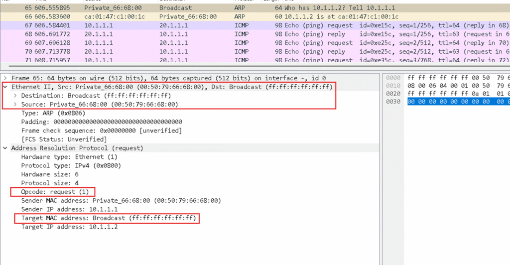
PC1 broadcasts an ARP request on its local segment querying:
“Who has IP address 10.1.1.2? Tell 10.1.1.1.”
Because ARP requests are broadcast frames, all devices on the local network receive this request, but only the router with IP 10.1.1.2 responds.
Your Wireshark capture shows this ARP request sent from PC1, sent to the broadcast MAC address FF:FF:FF:FF:FF:FF.
The screenshot below shows that before the ICMP Echo Request is sent, PC1 first transmits an ARP Request to resolve the MAC address of its default gateway — the router’s IP address.

The screenshot below displays the detailed ARP Request packet sent by PC1 to discover the MAC address of its default gateway.
Step 3: ARP Reply from Router to PC1
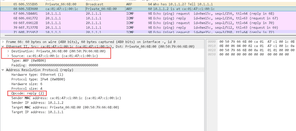
The router replies back with its MAC address, telling PC1:
“I am 10.1.1.2, and my MAC is ca01.47c1.001c.”
Upon receipt, PC1 updates its ARP table with:
- IP: 10.1.1.2
- MAC: ca01.47c1.001c
Now, PC1 can encapsulate packets destined for PC2 inside Ethernet frames targeted to the router interface.
Step 4: Packet Transmission from PC1 to Router
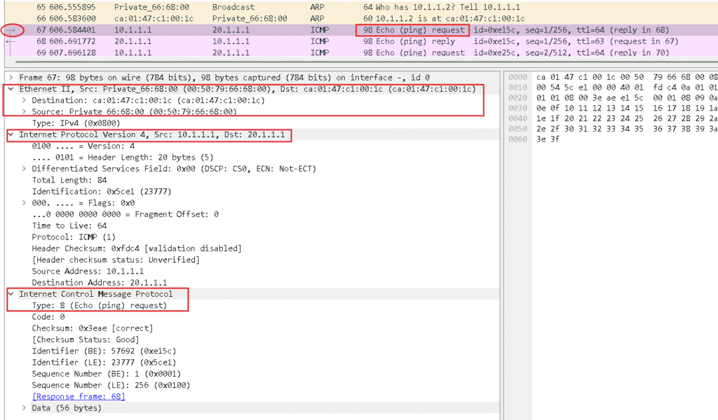
PC1 encapsulates the IP packet with:
- Source IP: 10.1.1.1
- Destination IP: 20.1.1.1 (PC2’s IP)
At the Ethernet frame level:
- Source MAC: PC1’s MAC (00:50:79:66:68:00)
- Destination MAC: Router’s G1/0 MAC (ca01.47c1.001c)
Now, the frame travels through the switch (assuming one is present) and reaches the router’s G1/0 interface.
| Device/Address | PC – 1 | PC – 2 | R1 interface G1/0 | R1 interface G2/0 |
| IP Address | 10.1.1.1/24 | 20.1.1.1/24 | 10.1.1.2/24 | 20.1.1.2/24 |
| MAC Address | 00:50:79:66:68:00 | 00:50:79:66:68:01 | ca01.47c1.001c | ca01.47c1.0038 |
Step 5: Router Receives and Processes the Packet
Upon receiving the frame, the router:
- Verifies the frame integrity (checks for errors).
- Strips the Ethernet header and inspects the IP packet inside.
- Looks at the destination IP (20.1.1.1) to decide where to forward the packet.
- Uses its routing table to determine that the packet should be sent out the G2/0 interface connecting to PC2’s subnet.
Before sending the packet, the router must know the MAC address of PC2.
Step 6: Router Uses ARP to Resolve PC2’s MAC
Since the router doesn’t yet know PC2’s MAC address, it sends an ARP request on the 20.1.1.0/24 network:
“Who has 20.1.1.1? Tell 20.1.1.2.”
PC2 responds with its MAC address (00:50:79:66:68:01), enabling the router to update its ARP cache.
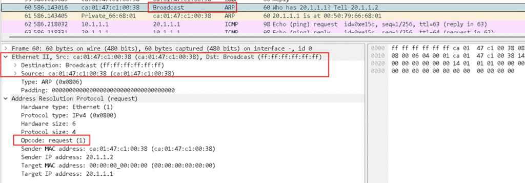
Step 7: Router Sends Packet to PC2
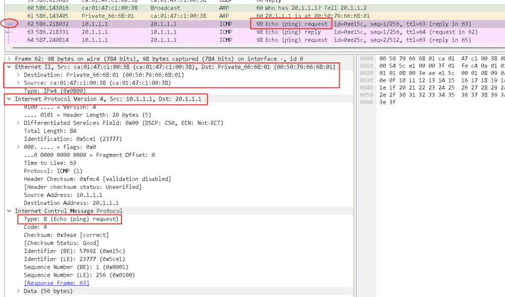
The router encapsulates the packet again into an Ethernet frame:
- Source MAC: Router’s G2/0 MAC (ca01.47c1.0038)
- Destination MAC: PC2’s MAC (00:50:79:66:68:01)
The frame is forwarded through the interface and reaches PC2.
ARP Table at Router end now –

Step 8: PC2 Receives and Responds
PC2 verifies the destination MAC and extracts the IP packet. After verifying the destination IP, it processes the ping request and sends a reply:
The reply packet goes back through the router following the reverse MAC and IP addressing steps.
Your ping results and Wireshark captures validate the successful packet exchange.
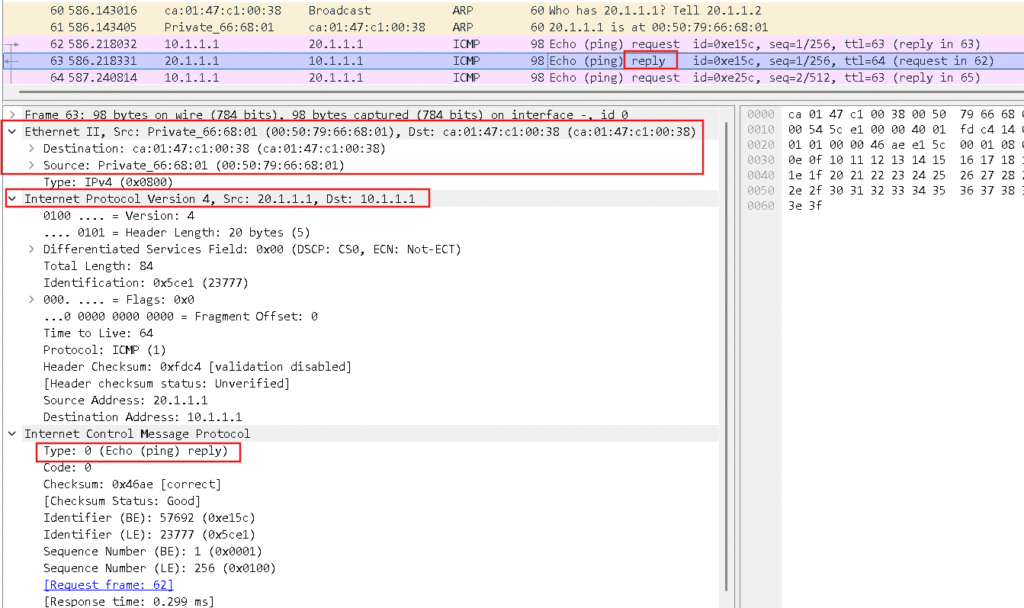
And Finally PC1 will ready to ping PC2 IP and here is the response –


Conclusion
This step-by-step demonstration shows in a clear way how packets flow between two PCs connected over different subnets through a router. Key takeaways include:
- PCs must resolve MAC addresses of their next-hop devices using ARP before forwarding packets.
- Routers perform routing decisions based on the destination IP address.
- At each hop, Ethernet frames are re-encapsulated with updated MAC addresses.
- This process ensures seamless communication across different networks.
Using your topology, configurations, ping results, and packet captures, this detailed explanation helps clarify what happens behind the scenes for network communication to work.

